- Analyzers
- Optics & Sources
- Technologies
- Support
- About
4 Ways to Effectively Monitor Total Chlorine in Liquid Hydrocarbons
Authors: Kyle Kuwitzky, Senior Product Manager and Leslie Johnson, Applications Scientist
BACKGROUND
Online Chlorine Analysis in Liquid Hydrocarbon Process Streams
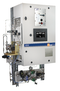
With ever-changing crude quality and blends, chlorine levels can shift quickly, making real-time analytical results invaluable. Clora® Online delivers realtime, continuous analysis of total chlorine from 0.2 ppmw up to 3000 ppmw. By monitoring desalted crude, a plant can optimize performance and immediately see impacts of crude changes (including organic chloride). Powered by MWDXRF®, Clora Online uses ASTM D7536 technology and is ATEX and NEC certified.

Corrosion at petroleum refineries is a critical problem all over the world. In the United States alone, NACE International, a professional association dedicated to reducing the economic impact of corrosion, has shown that $3.7 billion in direct costs are realized annually from maintenance, vessel expenditures, and fouling as a result of corrosion.1 This huge figure does not take into account the estimated loss of as much as $12 billion in profits due to decreased capacity, unit outages, and premature turnarounds that result from corrosion.2
CHALLENGE
Chlorine in crude oil, if not removed, can hydrolyze during processing to form hydrochloric acid. The crude oil desalter is the first line of defense in the prevention of corrosion, but in order to provide a proper defense, an effective chloride monitoring solution must be implemented. Many refiners rely on semi-periodic testing of inorganic chlorides to get the job done. However, what if a desalter upset occurs in between testing periods? Worse yet, what if an organic chlorine slug is present in the incoming crude? The desalter will remove only the extractable inorganic chlorides, not organic chlorides, and any chlorides that pass through the desalter have the potential of causing fouling and corrosion issues.
Even refiners who don’t rely on semi-periodic testing typically only monitor inorganic chlorine. While this is very important for desalter efficiency, it does not capture all threats.
INTRODUCTION
Since its launch in 2007, Clora® Benchtop Analyzer has been widely adopted by refineries and test labs for monitoring chlorine in petroleum. With over 200 systems in the field, XOS customers know they can trust Clora for testing products from crude oil to naphtha cuts and VGO. In 2011, XOS launched Clora Online; an online analyzer that delivers continuous, real-time chlorine analysis in liquid hydrocarbon and aqueous process streams.
In this paper, we will discuss the most popular Clora benchtop and online procedures utilized by petroleum laboratories around the world to measure total chlorine for corrosion mitigation:
- Organic Chlorides by ASTM D4929
- Total Chlorine by Modified ASTM D7536 with Accu-flow
- Online Chlorine Analysis in Crude Oil and Petroleum Process Streams
- Organic and Inorganic Chlorides Using Water Extraction
1. Koch, Gerhardus H., et. Al. “Corrosion Costs and Preventive Strategies in the United States.” NACE International.
2. “Petroleum Refinery Gap Analysis.” NACE Technical Coordination Committee, 18 Oct. 2008.
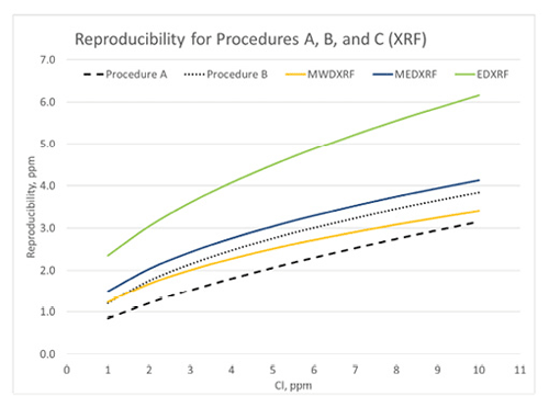
Figure 1: D4929 Reproducibility
1. ORGANIC CHLORIDES BY ASTM D4929
On October 15, 2017, ASTM approved the addition of Procedure C to D4929 Standard Test Method for Determination of Organic Chloride Content in Crude Oil. Procedure C uses X-ray Fluorescence (XRF) to determine the chlorine content in the crude oil naphtha fraction. This is an important step forward, as users will be able to officially use XOS’ Clora, Clora 2XP, and Sindie +Cl analyzers for organic chloride analysis in crude oil without ASTM method modification.
Traditionally, users of D4929 distill a crude oil sample to 400°F, wash the resulting naphtha fraction by caustic to remove H2S and then water to remove inorganic chlorides, and then use Procedure A or Procedure B to determine chloride content. Chloride content of the crude is then determined by back calculation. Procedure A determines chloride content by sodium biphenyl reduction followed by potentiometry, and Procedure B uses combustion and microcoulometry to determine chloride content in the naphtha fraction.
Figure 2: D4929 Repeatability
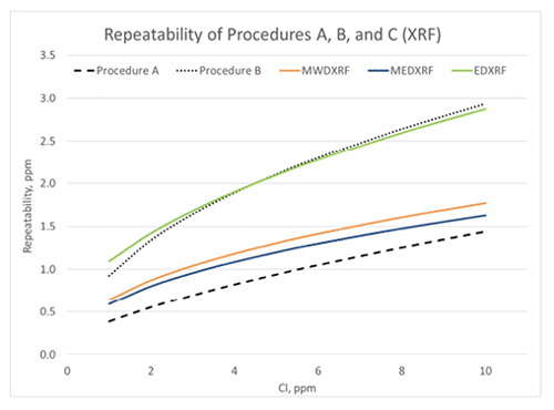
Procedure C test method precision was determined by an interlaboratory study (ILS) designed to replicate the original D4929 Precision A and B ILS. Eight ILS participants distilled ten crude oil blends of varying nominal organic chloride concentrations in blind duplicate, and the resultant naphtha cuts were washed and analyzed by multiple XRF techniques. The Procedure C precision varied by XRF type, and as a result there are separate precision statements for MWDXRF, MEDXRF, and EDXRF. Figures 1 and 2 compare the calculated precision statements obtained from the Procedure C study with the original Procedure A and B precision statements.
Figure 1 illustrates the calculated reproducibility for all D4929 procedures using the published precision statements in D4929. It demonstrates that Clora (MWDXRF) has better reproducibility than the other Procedure C XRF techniques and exhibits equivalent or better reproducibility than Procedure B (microcoulometry). In a recent review of the ASTM crude oil proficiency testing program, Procedure B is the most commonly used procedure for organic chloride analysis, though this may change with the addition of Procedure C to D4929. Figure 2 illustrates the calculated repeatability for all of the D4929 procedures, and Procedure C MEDXRF and MWDXRF (Clora) consistently exhibit better repeatability than Procedure B.
The addition of Procedure C to D4929 provides a precise, easy to use alternative to Procedures A and B. Clora, Clora 2XP, and Sindie +Cl analyzers comply with D4929 Procedure C.
2. TOTAL CHLORINE BY MODIFIED ASTM D7536 WITH ACCU-FLOW
X-ray Fluorescence (XRF) spectrometry, while widely used for total sulfur testing, has traditionally been an ineffective tool for the direct measurement of total chlorides in crude oil due to the settling effects of inorganic chloride salts during the measurement process. This settling leads to poor precision and an industry preference for other measurement or sample extraction techniques.
To address the effects of particulate settling, XOS introduced a continuous sample flow option to their Monochromatic Wavelength Dispersive XRF (MWDXRF) benchtop chlorine spectrometer: Clora with Accu-flow. The Accu-flow process uses a stepper motor for continuous injection of crude oil during the sample measurement, eliminating the settling of inorganic chloride salts. This process allows for the direct measurement of total chlorine without water wash extraction or sample distillation, as in ASTM D4929, and delivers results in just minutes.
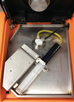
The Accu-flow design works for crude oils with a maximum viscosity of 2000 cSt at 70°F. A 60 ml crude oil sample is injected at a 20 ml / min flow rate into the yellow tubing shown in Figure 3. The sample flows from the yellow tubing through the Accu-flow insert assembly, where the sample is exposed to X-rays. The sample then flows through the black drain tube and is collected outside the analyzer. Typical measurement time is three minutes. Depending on the crude viscosity and rate of inorganic chloride settling, the difference between static and Accu-flow measurement results can be quite dramatic. In the following examples, four samples of two crude oils have been run either statically or using Accu-flow for a three minute measurement time. In order to illustrate the behavior of chlorine during the measurement, 30-second data points have been taken within the three minute measurement interval and graphed accordingly. Figures 4 and 5 show the static measurement increasing over time, leading to an inaccurate total chlorine measurement. However, the Accu-flow measurement remains stable throughout the measurement period and is repeatable over multiple measurements, as seen in Table 1.
Figure 3
| Table 1: Average Chlorine Concentration of Accu-flow Repeats | ||
|---|---|---|
| Flow Sample | Aasgard Crude Chlorine (ppm) | Bonga Crude Chlorine (ppm) |
| 1 | 55.9 | 82.9 |
| 2 | 55.1 | 84.2 |
| 3 | 54.9 | 83.8 |
| Average | 55.3 | 83.6 |
| Std. Dev | 0.53 | 0.67 |
| %RSD | 0.96% | 0.80% |
Figure 4: Chlorine in Aasgard Crude Oil
Static vs. Accu-flow
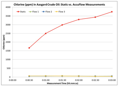
Figure 5: Chlorine in Bonga Crude Oil
Static vs. Accu-flow
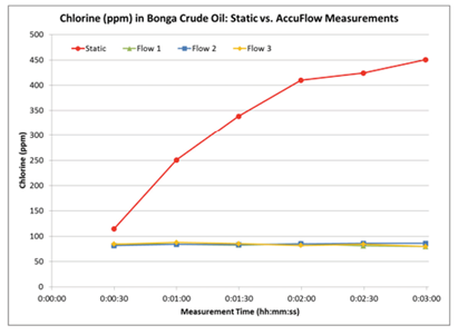
Figure 6: Low Level Cl in Desalted Crude
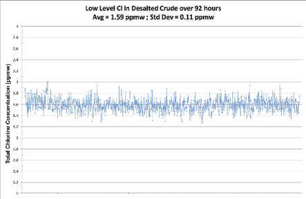
A closed loop sample of 1.59 ppmw was run through the analyzer for over 92 hours resulting in a standard deviation of 0.11 ppmw.
3. ONLINE CHLORINE ANALYSIS IN CRUDE OIL AND PETROLEUM PROCESS STREAMS
Before the launch of Clora Online, an effective online method for measuring Cl in a crude oil process stream did not exist. MWDXRF technology was developed in the past decade and has become a powerful online process tool for total sulfur analysis in product streams. However, online chlorine analysis in crude oil presents more challenges due to low-level quantification requirements and sampling complications. To meet these needs, XOS has developed a MWDXRF online chlorine analyzer.
Clora Online uses ASTM D7536 technology and delivers real-time, continuous analysis of total chlorine with an LOD of 0.2 ppmw in hydrocarbons and 0.6 ppmw in aqueous process streams. Results are delivered every 15-300 seconds, depending on user preference. Clora Online offers extended range up to 3000 ppmw allowing for the detection of a chloride spike, which may indicate an upset in the desalting process or the presence of an organic slug. This enables refiners to act quickly and avoid potential hazards. Figures 6, 7, and 8 demonstrate Clora Online’s precision, stability, and reliability.
Figure 7: Cl in Water Upset Simulation
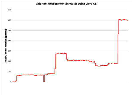
This graph depicts a closed loop water sample that was spiked and diluted at different times. The results demonstrate fast response time and resilience during upset conditions.
The sample stream flows through a Dynamic Window Module (DWM) and outside of the analyzer chamber, protecting the electronic equipment inside. With no sample conversion required, the sample flows through the analyzer cell and back into the process stream or to a sample recovery system, depending on site conditions. At user defined intervals, the sample lines are purged in order to allow the DWM to perform a film advance, where the X-ray transparent polyimide film used to contain sample will be rolled across the sample window to introduce clean film. This automated process eliminates the need for manual intervention and frequent calibration. The high viscosity DWM allows for sample viscosities up to 160 cSt at 275° F, and enables the measurement of viscous material.
Because of its high-precision and superior detection limit, Clora Online not only provides an effective tool for salt content monitoring but also serves as an important process control tool for chlorine content in desalted crude and other process streams further downstream in the refinery process.
Visit https://www.xos.com/resource-petroleum for more information and to download the complete whitepaper: Online Chlorine Analysis in Crude Oil and Petroleum Process Streams.
Figure 8: Cl in Crude over 8-day Period
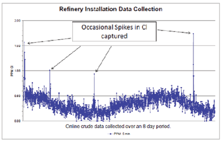
This graph shows refinery data collected over an 8 day period, where detected spikes in Cl allowed for immediate intervention to prevent potential hazards.
4. ORGANIC AND INORGANIC CHLORIDES USING WATER EXTRACTION
Although all XRF techniques are capable of only total elemental analysis, with some sample preparation, Clora, Clora with Accu-flow, Clora 2XP, and Sindie +Cl can also be used to characterize inorganic and organic chlorides in crude oil. Using a hot water extraction, crude oil may be separated into its organic chloride and inorganic chloride constituents with the organic chlorides staying in the crude oil layer and the inorganic chlorides precipitating into the water layer. Clora can then be used to measure each layer to determine organic and inorganic chlorides. While many laboratories have successfully used this sample preparation technique, unfortunately, this technique has crude-dependent limitations. Not all crude oils are easily extracted and this sample preparation technique has variable within-lab repeatability and poor between-lab reproducibility.
Procedures A-C will assist the user in separating chlorine in crude oil into its organic and inorganic counterparts using water extraction methods.
Procedure Notes:
- Note 1: Be sure to prepare the crude/solvent mixture by weight, not volume.
- Note 2: DI water and toluene or xylene should be analyzed by Clora prior to use to check for chlorine contamination. Any chlorine contamination in the DI water should be subtracted from the inorganic chlorine result, and any chlorine contamination from the solvent should be subtracted from the organic chlorine result.
- Note 3: Assuming the density of water = 1 g/ml, then weight equals volume. Therefore, 75 ml water = 75 g.
- Note 4: Some customers using paper filters, such as Whatman 125 mm grade 1 filter paper circles, have reported that the filter paper can add to the chlorine content. This can be verified by testing chlorine levels in DI water before and after filtration. Subtract any interferences from the inorganic chlorine result.
- Note 5: When pipetting the water sample, expel air from the pipette when initially putting it into the water sample to keep oil (often present as a thin film on the surface of the water) out of the measured sample cup.
- Note 6: When calculating inorganic chlorine, use the weight of the crude in the calculation. Do not use the combined weight of the solvent and crude.
PROCEDURE A: Crude Oil Sample Preparation
Depending on crude type and composition, it may be hard to obtain a stable homogenous sample. Viscous or asphaltene and bitumen containing crudes are particularly difficult to water extract. The addition of toluene or xylene to these types of crudes will increase the solubility of heavier crude components leading to a more homogenous, less viscous sample that is more efficiently water extracted.
Prepare approximately 25 ml of 50/50 wt% crude to solvent (toluene or xylene) mixture per Note 1. Shake or homogenize the crude oil sample prior to obtaining a specimen for dilution. A 12.5 g crude to 12.5 g solvent mixture will work well for most crudes. See Note 2 regarding chlorine contamination in solvents. When analyzing chlorine content with Clora, remember to multiply the measured results by 2 to account for this dilution.
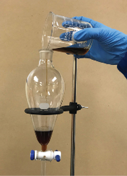
Separatory Funnel
PROCEDURE B: Water Extraction Using a Separatory Funnel
Weigh 25 grams of crude into a separatory funnel. Make sure to shake or homogenize the crude oil sample before obtaining a specimen. Add 75 ml (see Note 3) of boiling DI water. For solvent diluted crudes, use 25 grams of crude/solvent mixture (as prepared in the Crude Oil Sample Preparation section) to 75 ml boiling DI water.
Cap the separatory funnel and shake vigorously for two minutes. Periodically degassing the sample by venting the stopcock will prevent gas buildup. Let the sample sit undisturbed for ten to fifteen minutes. Carefully pipette a sample of the crude for Clora analysis, making sure to take the sample from the middle of the sample layer without picking up contamination from the water phase. Drain the water sample from the bottom of the separatory funnel for Clora analysis. It is important to make sure there are no particulates present in the water sample, so filter if necessary (see Note 4).
PROCEDURE C: Organic, Inorganic, and Total Chlorine Analysis with Clora
In general, pipette 5-8 ml of sample into a sample cup and test with Clora using XRF film (Etnom for Clora and Sindie +Cl, Prolene for Clora 2XP). Remember to punch a vent hole in the sample cup. The standard analysis time for samples containing >1 ppm chlorine is 300 s. If the sample contains <1 ppm chlorine, a 600 s measurement time is suggested for optimal results with Clora and Sindie +Cl. For samples containing <0.5 ppm chlorine measured with Clora 2XP, measure two samples (new sample cup each time) for 300 s each and use the average of the two results. If the two results have a ≥0.2 ppm difference, measure a third sample to determine which of the two samples is an outlier. Discard any outlier measurement results.
In addition, if the sample contains >0.5 wt% sulfur (>0.1 wt% sulfur when measuring with Clora 2XP), use of sulfur correction may improve the accuracy of the results.
Analyze a blank solvent sample (if diluting crude sample) and a blank DI water sample to account for any diluent interferences (see Note 2).
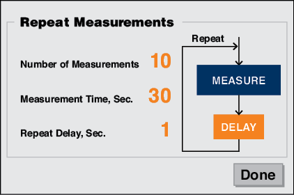
Analyze the crude phase to quantify the amount of organic chlorine (and non-extractable inorganic chlorine) in the crude sample. In order to ensure the extraction process has been successful, check the crude or crude/solvent mixture for settling while performing the measurement. To do this, divide the recommended measurement time (as described above) into 30 or 60 second repeats, noting that the maximum repeat input with Clora and Clora 2XP analyzers is 10 repeats. Run the sample accordingly and look for increasing measurement values within the individual sample repeats. Continually increasing measurement values indicate an incomplete extraction. A second (or third) extraction may be necessary.
For example, on the repeats screen below, if the recommended measurement time is 300 s, run (10) 30-second repeats on one sample and examine the individual repeat measurements for upward trending. If the total measurement time is 600 s, run (10) 60-second repeats. Keep the repeat delay at 1 second. Don’t forget to use sulfur correction if necessary.
If the measurement results indicate trending (crude B in Table 2), return the crude or crude/solvent sample to the separatory funnel or centrifuge tube and extract again using a new aliquot of hot DI water. If the measurement results indicate a successful extraction (crude A in Table 2), use the average measurement result and the following equations to calculate organic chlorine:
| Table 2 | |||||
|---|---|---|---|---|---|
| Settle Time | Sample | Crude A | Crude B | ||
| hh:mm:ss | Repeat | Cl (ppm) | cts/30s | Cl (ppm) | cts/30s |
| 0:00:30 | 1 | 2.51 | 81 | 36.15 | 960 |
| 0:01:00 | 2 | 3.28 | 101 | 35.31 | 938 |
| 0:01:30 | 3 | 2.59 | 83 | 37.91 | 1006 |
| 0:02:00 | 4 | 2.51 | 81 | 44.76 | 1185 |
| 0:02:30 | 5 | 2.51 | 81 | 52.00 | 1374 |
| 0:03:00 | 6 | 3.39 | 104 | 55.52 | 1466 |
| 0:03:30 | 7 | 2.47 | 80 | 59.88 | 1580 |
| 0:04:00 | 8 | 3.24 | 100 | 63.86 | 1684 |
| 0:04:30 | 9 | 2.97 | 93 | 65.85 | 1736 |
| 0:05:00 | 10 | 2.90 | 91 | 76.87960 | 2024 |
| Average | 2.84 | 52.81 | |||
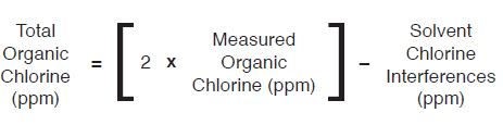
EQUATIONS TO CALCULATE ORGANIC CHLORINE
- For undiluted crude samples:
- For 50/50 wt% diluted crude samples:
The water phase of the sample is measured to quantify the amount of inorganic chlorine in the crude sample. Pipette a water sample for analysis (see Note 5).
Particulate matter, if present in the sample, will often be in the water layer. Filter the sample if necessary (see Note 4). Cloudy water is normal and does not require filtration.
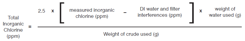
It is best to use a water based calibration curve to test low chlorine concentration water samples in order to compensate for oxygen absorption effects. High oxygen content, if not accounted for, will result in reduced counts and a falsely low chlorine value. If a dedicated water curve has not been developed, multiply the results obtained using a hydrocarbon calibration curve by 250% (i.e. 2.50).
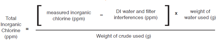
To account for the dilution of the inorganic crude chlorine into the water phase of the sample, we will use the following equations to calculate inorganic chlorine. If running multiple extractions, combine the extraction water, mix well, and measure sample per directions above. Remember to use the total weight of water used for extraction. See Note 3 regarding the weight of water used for this calculation. See Note 6 regarding the use of crude weight vs. crude/solvent weight in the following inorganic chlorine calculations.
EQUATIONS TO CALCULATE INORGANIC CHLORINE
- For 50/50 wt% diluted crude or undiluted crude oil samples on water based curve:
- For 50/50 wt% diluted crude samples or undiluted crude oil samples on hydrocarbon based curve:
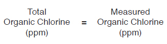
To obtain total chlorine, simply add inorganic and organic results together.
CONCLUSION
Corrosion mitigation strategies are an important part of ensuring safe refinery operation and maximizing profitability. Clora has become a critical part of identifying potential corrosion events and monitoring the effectiveness of these mitigation strategies. With over a decade of experience supporting refiner’s needs to monitor chlorine, XOS can provide many different solutions for monitoring organic, total, and inorganic chlorine in crude oil.
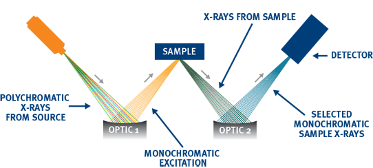
ADVANCED ANALYSIS WITH MWDXRF
Monochromatic Wavelength Dispersive X-ray Fluorescence (MWDXRF) utilizes state-of-the-art focusing and monochromating optics to increase excitation intensity and dramatically improve signal-to-background ratio compared to traditional WDXRF instruments. This enables significantly improved detection limits, precision, and a reduced sensitivity to matrix effects. A monochromatic and focused primary beam excites the sample and secondary characteristic fluorescence X-rays are emitted from the sample. A second monochromating optic selects the chlorine characteristic X-rays and directs these X-rays to the detector. MWDXRF is a direct measurement technique and does not require consumable gasses or sample conversion delivering robust and low maintenance analyzers with dramatically lower detection limits and faster response times.
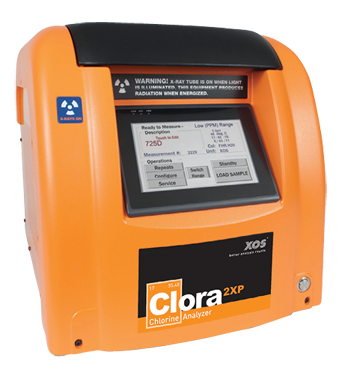
Clora 2XP delivers twice the precision for total chlorine analysis in liquid hydrocarbons such as aromatics, distillates, heavy fuels and crude oils, as well as aqueous solutions. Compliant with ASTM D7536 and D4929 methodology, Clora 2XP is ideal for testing related to catalyst poisoning in reformers, and sites with catalytic crackers and hydrocrackers. In addition, its automatic sulfur correction is perfect for high sulfur and low chlorine applications, such as crude oil and VGO. Powered by MWDXRF, Clora 2XP does not require gasses or high temperature processes, equating to easy operation and minimal maintenance requirements.
REFERENCES
NACE International, Effect of Nonextractable Chlorides on Refinery
Corrosion and Fouling, NACE International Publication 34105, Item 24226.